
At a Glance
A free-body diagram isolates one object and draws each force on it as a labeled arrow starting at the object. Adding the arrows gives the net force, and Newton's second law, F_net = m a, turns that net force into an acceleration.
- Also called
- FBD, force diagram
- Shows
- Every external force on one chosen object
- Arrows
- Direction of each force; length grows with size
- Usual forces
- Weight, normal force, friction, tension, applied push or pull, drag
- Used with
- Fnet = ma (Newton's second law)
- Unit on labels
- newton (N)
On this page
- What Is a Free-Body Diagram?
- Free-Body Diagrams Explained Simply
- How Do You Draw a Free-Body Diagram Step by Step?
- Which Forces Belong on a Free-Body Diagram?
- How Do Free-Body Diagrams Connect to Newton's Second Law?
- What Are Some Common Free-Body Diagram Examples?
- How Do You Draw a Free-Body Diagram on an Incline?
- What Mistakes Do Students Make With Free-Body Diagrams?
- Going Deeper: When Does a Dot Stop Being Enough?
- Practice Drawing Free-Body Diagrams
- Key Facts
- Quiz
- FAQ
What Is a Free-Body Diagram?
A free-body diagram is a picture of a single object with every force on it drawn as an arrow. The word "free" means the object is cut free from its surroundings: the floor, ropes, hands and air are left out, and only the forces they exert remain. Each arrow starts at the object, points the way the force pushes or pulls, and carries a label such as W for weight or N for normal force.
The object is often shrunk to a dot or a simple box. That is fine for most problems, because we only care about how the object as a whole speeds up, slows down or turns a corner. When rotation matters, as with a ladder leaning on a wall, the arrows are placed where each force really acts.
Free-body diagrams are the first step in almost every mechanics problem. They turn a messy real scene into a tidy list of forces that you can add like vectors.
Free-Body Diagrams Explained Simply
Imagine taking a photo of a sled being pulled across snow, then erasing everything except the sled. Now draw an arrow for every push or pull on it: gravity pulling down, the snow pushing up, the rope pulling forward and friction dragging back. That sketch is a free-body diagram.
Big forces get long arrows and small forces get short ones. If the arrows cancel out in every direction, the sled keeps moving the same way it was moving, or stays still. If one side wins, the sled speeds up toward the winning side.
How Do You Draw a Free-Body Diagram Step by Step?
- Pick one object. Decide exactly what your system is, such as "the crate" or "the lamp," and draw it as a box or dot.
- Add the weight. Every object near Earth has a downward arrow of size
- Find every contact. Each surface, rope, hand or spring that touches the object adds a force. Surfaces give a normal force at right angles to themselves, and possibly friction along them.
- Add non-contact forces. Check for magnetic or electric forces, and air drag if the object moves fast.
- Label and size the arrows. Give each a symbol and, where known, a value in newtons. Make larger forces longer.
- Choose axes. Usually horizontal and vertical, but tilted along the surface for a slope.
Leave out forces the object exerts on other things. Those belong on the other object's diagram.
Which Forces Belong on a Free-Body Diagram?
A handful of forces cover nearly every school and college problem. The table below lists them with their usual symbols and directions. The weight is always there near Earth, and it is a force in newtons, not a mass in kilograms (see mass vs weight). The normal force appears whenever the object rests on or presses against a surface. Tension comes from ropes, cables and chains, and it always pulls along the rope, never pushes.
Friction acts along a surface and opposes slipping, while air resistance opposes motion through the air. Anything else, such as a hand push or an engine thrust, is usually called an applied force.
| Force | Usual symbol | Direction | When to draw it |
|---|---|---|---|
| Weight (gravity) | W, Fg or mg | Straight down, toward Earth's center | Always, for any object near Earth |
| Normal force | N or FN | Perpendicular to the surface, away from it | Whenever the object presses on a surface |
| Static friction | fs | Along the surface, opposing the slip that would happen | Surfaces touching but not sliding |
| Kinetic friction | fk | Along the surface, opposite the sliding | Surfaces sliding over each other |
| Tension | T or FT | Along the rope, away from the object | A rope, cable or chain is attached |
| Applied force | Fapp | Whichever way the push or pull acts | A person or machine pushes or pulls |
| Air resistance (drag) | FD | Opposite the motion through the air | Fast motion or light objects |
| Spring force | Fs | Back toward the spring's natural length | A stretched or compressed spring is attached |
| Buoyant force | FB | Straight up | The object sits in a liquid or gas |
| Source: Standard force symbols used in introductory mechanics · Retrieved October 2026 | |||
How Do Free-Body Diagrams Connect to Newton's Second Law?
The diagram's job is to give you the net force, the vector sum of all the arrows. Newton's second law then says
When an object rests or moves at constant velocity, its acceleration is zero and the arrows must cancel. That condition, called translational equilibrium, is how you find unknown forces such as the tension in a cable. When the arrows do not cancel, the object accelerates toward the side with the larger total, as in the crate example below.
Once the diagram is drawn, this is the equation you apply along each direction, using the net force you read off the arrows.
| Symbol | Quantity | SI unit |
|---|---|---|
| net external force | newton (N) | |
| mass | kilogram (kg) | |
| acceleration | meter per second squared (m/s²) |
Rearranged to find another variable:
Valid for: constant mass, inertial reference frame; vector equation (a points along F_net).
Example 1 A crate pushed across a floor
A mover pushes a 40 kg crate across a level floor with a horizontal force of 180 N, while kinetic friction acts backward with 110 N. The weight and normal force cancel. What is the crate's acceleration?
- Given:
- F_push:
- f_k:
- mass:
- F_push:
- Formula:
- Substitute:
- Answer:
The diagram shows that only the 70 N left over after friction speeds the crate up, not the full 180 N push.

What Are Some Common Free-Body Diagram Examples?
A few situations come up again and again, and each has a recognizable diagram:
- A book on a table: weight down, normal force up, equal in size. Two arrows, net force zero.
- A hanging lamp: weight down, tension up, also equal when the lamp is still.
- A crate being pushed: weight and normal force cancel vertically, while the push and friction compete horizontally.
- A falling skydiver: weight down and air drag up. The drag grows with speed until the arrows match and the speed stops rising.
- A car on a curve: sideways friction from the tires points toward the center of the turn and keeps the car on its path.
Notice that the arrows describe forces, not motion. A ball thrown upward has only a downward weight arrow once it leaves your hand, even while it is still rising.
Example 2 A pendant lamp hanging still
A 3.2 kg pendant lamp hangs at rest from a single cord over a dining table. Its free-body diagram has only two arrows: weight down and cord tension up. How large is the weight, and therefore the tension?
- Given:
- mass:
- acceleration due to gravity:
- mass:
- Formula:
- Substitute:
- Answer:
Because the lamp is not accelerating, the two arrows must be equal in length, so the tension equals this weight.


How Do You Draw a Free-Body Diagram on an Incline?
On a slope, the weight still points straight down, but the normal force tilts with the surface and friction runs along it. The trick is to rotate your axes so one lies along the slope and the other is perpendicular to it. Then the weight splits into two parts:
The normal force balances the pressing part, so
Example 3 A box sliding down a smooth ramp
A 6 kg box slides down a smooth ramp tilted at 20°, with friction small enough to ignore. Using tilted axes, what is the net force on the box along the slope?
- Given:
- mass:
- g:
- θ:
- mass:
- Formula:
- Substitute:
- Answer:
The normal force cancels the part of the weight pressing into the ramp, so only the downhill component mg sin θ is left over.

What Mistakes Do Students Make With Free-Body Diagrams?
The most common slip is adding a "force of motion" in the direction the object is moving. Motion does not need a force to continue; only changes in motion do. Another is drawing the reaction forces from Newton's third law on the same diagram. The floor pushes up on the crate, and the crate pushes down on the floor, but only the first one belongs on the crate's diagram.
Students also tend to assume the normal force always equals the weight. It does only on a level surface with no other vertical pushes or pulls. Press down on a box, tilt the floor or ride in an accelerating elevator, and the normal force changes.
Myth: A moving object needs a forward force arrow to keep moving.
Physics: Motion continues without any force. A forward arrow appears only if something actually pushes or pulls the object forward.
Myth: The normal force always equals the object's weight.
Physics: That is only true on a level surface with no other vertical forces. On a slope it is mg cos θ, and an extra downward push makes it larger.
Myth: Both forces of a Newton's third law pair go on the same diagram.
Physics: The two forces in a pair act on different objects, so each one goes on a different object's diagram.
Myth: At the top of its flight, a thrown ball has no forces on it.
Physics: Gravity still pulls it down with its full weight. Only its vertical velocity is zero for an instant.
Going Deeper: When Does a Dot Stop Being Enough?
Treating the object as a point works when only its overall motion matters. If you need to know whether it will tip or spin, each force must be drawn at its actual point of contact, because forces acting off-center create torque. A ladder against a wall, a door on hinges and a seesaw all need this extended-body version.
For systems of several objects, such as two blocks joined by a string, you can draw one diagram per object or one for the whole group. Internal forces like the string tension cancel inside the group diagram, which is a handy shortcut for finding the shared acceleration first.
Practice Drawing Free-Body Diagrams
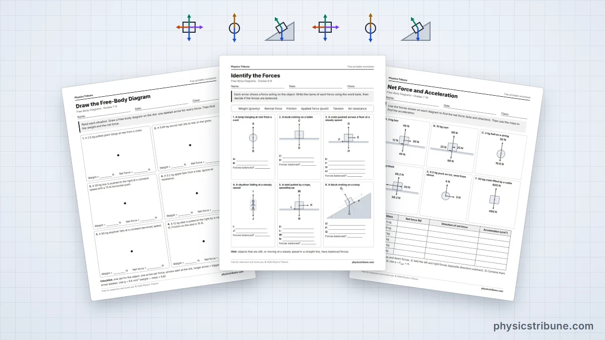
Drawing diagrams is a skill that improves quickly with practice. Our printable free-body diagram worksheets start with identifying forces and build up to ramps with friction, each with an answer key. Once you have a net force, the force calculator checks your F = ma step, and the force formulas sheet keeps the key equations in one place. The laws behind all of this were set out by Isaac Newton in 1687.
Key Facts
- A free-body diagram shows one object alone, with an arrow for every force acting on it.
- Each arrow points in the direction of its force, and longer arrows mean larger forces.
- Weight always points straight down, and the normal force always points perpendicular to the surface.
- Only forces acting on the chosen object belong on its diagram, never forces it exerts on other things.
- Adding the arrows gives the net force, and Newton's second law turns that into acceleration with F_net = ma.
- If all the arrows cancel, the object is in equilibrium: at rest or moving at constant velocity.
- On a slope, tilted axes split the weight into mg sin θ along the surface and mg cos θ into it.
Quick Quiz: How Well Do You Know Free-Body Diagrams?
6 questions. Tap an answer to check it.
A book rests on a level table. Which forces belong on the book's free-body diagram?
Gravity pulls the book down and the table pushes it up; the book's push on the table acts on the table instead.
Which direction does the normal force point on a box resting on a ramp?
The normal force is always at right angles to the surface that exerts it.
A 10 kg cart is pulled right with 50 N against 20 N of friction. What is the net force?
The forces point in opposite directions, so subtract: 50 N minus 20 N leaves 30 N to the right.
A ball has been thrown straight up and is still rising. Ignoring air, what does its free-body diagram show?
Once the ball leaves the hand, gravity is the only force acting on it.
If every arrow on a free-body diagram cancels, what can you conclude?
Zero net force means zero acceleration, so the object is either at rest or moving at constant velocity.
On a ramp tilted at angle θ, which part of the weight pulls an object down the slope?
Resolving the weight along tilted axes gives mg sin θ along the slope and mg cos θ into it.
Frequently Asked Questions
What is a free-body diagram in simple terms?
It is a quick drawing of one object with arrows showing every push and pull on it. You leave out the surroundings and keep only the forces they apply. The direction of each arrow shows which way the force acts, and its length shows roughly how strong it is. The drawing makes it easy to see whether the forces balance or not.
What is the purpose of a free-body diagram?
It organizes all the forces on an object so you can add them correctly. Without a diagram it is easy to forget a force or count one twice. Once the arrows are drawn, you can find the net force in each direction and apply Newton's second law to get the acceleration, or set the net force to zero to find an unknown force.
What forces are included in a free-body diagram?
Include every force that other things exert on your chosen object. Near Earth that always means weight. Add a normal force for each surface it touches, friction where surfaces could slip, tension for each attached rope, and any applied pushes or pulls. Add drag for fast motion and buoyancy for objects in water. Leave out forces the object exerts on anything else.
Do you include velocity or acceleration on a free-body diagram?
No, a free-body diagram shows forces only. Velocity and acceleration are not forces, so they do not get force arrows. Some teachers ask you to draw a separate small arrow beside the diagram to show the direction of acceleration, which is a useful check: it should point the same way as the net force from your diagram.
How do you find the net force from a free-body diagram?
Choose axes, then add the forces along each axis, counting one direction as positive and the opposite as negative. For a box pushed right with 50 N against 20 N of friction, the horizontal net force is 30 N to the right. If forces act at angles, split each into horizontal and vertical parts first, then add the parts separately.
What is the difference between a free-body diagram and a force diagram?
The names are often used for the same thing. Some textbooks use force diagram for a sketch of a whole scene with forces drawn on several objects, and keep free-body diagram for a single object drawn on its own. The single-object version is the one you need for applying Newton's second law, because it shows exactly which forces act on that object.
Which way does the normal force point on a free-body diagram?
The normal force always points perpendicular to the surface and away from it, pushing the object out of the surface. On a flat floor that means straight up. On a ramp it tilts back from vertical by the same angle as the ramp. On a wall it points sideways, away from the wall.
How long should the arrows be on a free-body diagram?
Arrows should be roughly proportional to the size of the forces. If two forces are equal, make their arrows the same length. If one force is twice another, draw it about twice as long. Perfect scale is not required in most classes, but sensible lengths help you spot right away whether the forces balance or which way the object will accelerate.
Keep Exploring







Sources
Constants come from NIST CODATA 2022 (public domain) and unit definitions from the BIPM SI Brochure (CC BY 4.0). Text, diagrams and illustrations are original work by Physics Tribune.