
At a Glance
Capacitors are classified by their dielectric: ceramic, electrolytic (aluminum and tantalum), film, mica, supercapacitors and variable types. For a parallel-plate design, C = κ ε0 A / d, so a dielectric with a larger constant κ, a bigger plate area A and a thinner gap d all raise the capacitance. Electrolytic and most supercapacitors are polarized and must be connected the right way around.
- Classified by
- Dielectric material, polarity, fixed or variable
- SI unit
- farad (F); parts usually in pF, nF or μF
- Key formula
- C = κ ε0 A / d
- Polarized types
- Aluminum electrolytic, tantalum, most supercapacitors
- Smallest values
- About 1 pF (ceramic, mica, air)
- Largest values
- Thousands of farads (supercapacitors)
On this page
- How Are Capacitors Classified?
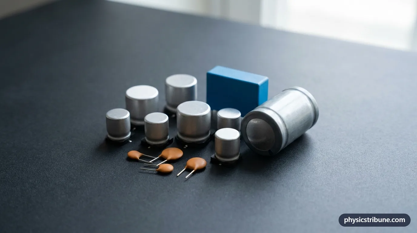
- Types of Capacitors Explained Simply
- Why Does the Dielectric Change the Capacitance?
- What Are Ceramic Capacitors?
- What Are Electrolytic and Tantalum Capacitors?
- What Are Film and Mica Capacitors?
- What Is a Supercapacitor?
- What Are Variable Capacitors?
- How Do You Choose the Right Type of Capacitor?
- How Do You Read Capacitor Markings?
- How Did Capacitor Types Develop?
- Practice and Next Steps
- Common Misconceptions
- Key Facts
- Quiz
- FAQ
How Are Capacitors Classified?
Every capacitor does the same basic job: it stores separated electric charge on two conductors with an insulator between them. What changes from one type to another is how that sandwich is built. Engineers sort capacitors in three main ways.
- By dielectric: ceramic, electrolytic oxide, plastic film, mica, glass, air or the double layer of a supercapacitor.
- By polarity: polarized capacitors have a marked positive and negative lead and must be connected the right way around. Non-polarized ones can go either way.
- By adjustability: most are fixed, but variable and trimmer capacitors can be tuned by turning a shaft or screw.
The dielectric is the most important choice, because it sets the capacitance per unit volume, the voltage limit, the stability with temperature and the cost.
Types of Capacitors Explained Simply
Think of capacitors as water tanks of different designs. Some are tiny but react instantly, like a cup you can fill and empty in a blink. Some are huge barrels that hold a lot but are slower and must be installed right side up. Some are precise measuring jugs that hold exactly the same amount whether the room is hot or cold.
Ceramic capacitors are the cups: small, cheap and fast. Electrolytic capacitors are the barrels: big storage, one correct way up. Film and mica capacitors are the measuring jugs: steady and accurate. Supercapacitors are a water tower, holding far more than any other capacitor, though at only a low pressure, meaning a low voltage per cell.
Why Does the Dielectric Change the Capacitance?
Capacitance measures how much charge a capacitor stores for each volt across it. For two flat plates, it depends on just three things: the plate area A, the gap d between them and the dielectric constant κ of the material in the gap. That relation,
A dielectric's molecules line up slightly in the electric field and partly cancel it, which lets more charge pile onto the plates for the same voltage. Air barely does this, so its κ is about 1. Plastic films reach 2 to 3, aluminum oxide about 9 and special ceramics into the thousands. Each capacitor type is basically a strategy for combining a good dielectric with a huge area and a tiny gap.
Every capacitor type is a variation on two conductors separated by an insulator, and this formula shows the three levers a designer can pull.
| Symbol | Quantity | SI unit |
|---|---|---|
| capacitance | farad (F) | |
| dielectric constant (1 for vacuum) | dimensionless (1) | |
| permittivity of free space (8.854 × 10⁻¹² C²/(N·m²) (F/m)) | coulomb squared per newton meter squared (C²/(N·m²)) | |
| plate area | square meter (m²) | |
| plate separation | meter (m) |
Rearranged to find another variable:
Valid for: plate separation small compared with plate size (edge effects neglected).
Example 1 Capacitance of a rolled film capacitor
A film capacitor is made by rolling up two metal layers separated by polypropylene film 5.0 μm thick. Unrolled, the overlapping area is 0.050 m², and polypropylene has a dielectric constant of about 2.2. What is its capacitance?
- Given:
- dielectric constant (1 for vacuum):
- permittivity of free space:
- plate area:
- plate separation:
- dielectric constant (1 for vacuum):
- Formula:
- Substitute:
- Answer:
Rolling the film is what fits a large plate area into a small cylinder; the result is a typical value for an audio or motor-run film part.
| Dielectric | Dielectric constant κ (about) | Capacitance for A = 1 cm², d = 10 μm (pF) |
|---|---|---|
| Vacuum | 1 (exact) | 88.5 |
| Air | 1.0006 | 88.6 |
| PTFE plastic | 2.1 | 185.9 |
| Polypropylene film | 2.2 | 194.8 |
| Polyester (PET) film | 3.3 | 292.2 |
| Mica | 6 | 531.3 |
| Aluminum oxide | 9 | 796.9 |
| Tantalum pentoxide | 27 | 2,390.6 |
| High-κ barium titanate ceramic | 1,000 to 5,000 | 88,541.9 to 442,709.4 |
| Source: Dielectric constants are typical room-temperature values · capacitance computed with C = κ ε0 A / d, ε0 from NIST CODATA 2022 · Retrieved October 2026 | ||

What Are Ceramic Capacitors?
Ceramic capacitors use a thin layer of ceramic, often based on barium titanate, as the dielectric. The modern form is the multilayer ceramic chip capacitor, a block smaller than a grain of rice built from many alternating layers of ceramic and metal electrode. There may be billions of them made every day, and a single phone contains hundreds.
They are non-polarized, cheap and respond very quickly, which makes them ideal for filtering fast electrical noise near chips. Low-κ ceramics are very stable with temperature and suit timing and tuning circuits. High-κ ceramics pack in more capacitance but lose some of it when warm or when a large DC voltage is applied, a trade-off designers must check.
Example 2 One layer of a ceramic chip capacitor
A ceramic chip capacitor has electrode layers that overlap over 4.0 × 10⁻⁶ m² (2 mm by 2 mm), separated by ceramic 5.0 μm thick with a dielectric constant of about 2,000. What is the capacitance of one layer?
- Given:
- dielectric constant (1 for vacuum):
- permittivity of free space:
- plate area:
- plate separation:
- dielectric constant (1 for vacuum):
- Formula:
- Substitute:
- Answer:
A real chip stacks dozens or hundreds of such layers in parallel, so their capacitances add and the tiny part reaches microfarads.
What Are Electrolytic and Tantalum Capacitors?
An aluminum electrolytic capacitor uses an aluminum foil whose surface is roughened and then coated with an extremely thin oxide layer. That oxide is the dielectric, and because it is so thin and the roughened foil so large, the part reaches hundreds or thousands of microfarads in a can the size of a thumb. A liquid or gel electrolyte serves as the second plate.
The catch is polarity. The oxide is only maintained when the foil stays positive. Connected backward, it breaks down, the capacitor heats up and it can vent or burst. The case is always marked with a stripe on the negative side, and in circuit diagrams the polarized symbol has one curved or marked plate.
Tantalum capacitors work on the same principle with tantalum metal powder and tantalum pentoxide, whose dielectric constant is higher still. They are smaller and more stable than aluminum types, which suits laptops and phones, but they also need correct polarity and careful voltage limits.
What Are Film and Mica Capacitors?
Film capacitors use thin plastic, such as polypropylene or polyester, between metal foils or metallized layers, all rolled or stacked together. They are non-polarized, handle high voltages well and change very little with temperature or age. You find them in audio crossovers, motor-run circuits for fans and air conditioners, and snubber circuits that absorb voltage spikes. Many metallized film types can even heal small breakdowns, as the thin metal around a fault vaporizes and isolates it.
Mica capacitors use thin sheets of the mineral mica, which splits naturally into very flat, uniform layers. Their capacitance is small, usually picofarads to a few nanofarads, but extremely precise and stable. That makes them a classic choice for radio-frequency oscillators and filters where the value must not drift.
What Is a Supercapacitor?
A supercapacitor, also called an ultracapacitor or electric double-layer capacitor, stores charge in a layer just a few molecules thick where a porous carbon electrode meets an electrolyte. The carbon has an enormous internal surface area, and the effective gap is tiny, so capacitances reach farads to thousands of farads.
The trade-off is voltage. Each cell is limited to around 2.5 to 3 V, so higher voltages need several cells in series. Supercapacitors charge and discharge in seconds and survive hundreds of thousands of cycles, so they back up memory chips, smooth bursts of power in camera flashes and catch braking energy in some buses and trams. Our energy stored in a capacitor page explains why storage grows with the square of the voltage.
Example 3 Energy in a supercapacitor cell
A 10 F supercapacitor cell is charged to its rated 2.7 V. How much energy does it store?
- Given:
- capacitance:
- voltage:
- capacitance:
- Formula:
- Substitute:
- Answer:
That is enough to light a small LED for several minutes, far more than any ordinary capacitor of the same size, but still much less than a battery holds.

What Are Variable Capacitors?
A variable capacitor has one set of plates that can rotate into or out of a fixed set, changing the overlapping area and therefore the capacitance. Old radios used large air-gap versions turned by the tuning knob to select a station, because the capacitance sets the frequency of the tuned circuit.
Trimmer capacitors are tiny versions adjusted once with a screwdriver during manufacture or repair. Modern electronics often replace both with varactor diodes, semiconductor junctions whose capacitance changes with the applied voltage.
How Do You Choose the Right Type of Capacitor?
Start with the capacitance and voltage the circuit needs, then pick a type whose range covers both with some margin. A rated voltage at least 20 to 50 percent above the highest voltage in the circuit is common practice. After that, consider polarity, size, stability and cost. The table below summarizes typical ranges for each family.
Timing behavior matters too. In a resistor-capacitor circuit, the time constant
| Type | Dielectric | Typical capacitance range | Typical voltage range | Polarized? | Common uses |
|---|---|---|---|---|---|
| Multilayer ceramic | Ceramic (often barium titanate) | About 1 pF to 100 μF | About 6 V to several kV | No | Noise filtering near chips, timing |
| Aluminum electrolytic | Aluminum oxide | About 0.1 μF to 1 F | About 6 V to 600 V | Yes | Power supply smoothing, audio coupling |
| Tantalum | Tantalum pentoxide | About 0.1 μF to 1,000 μF | About 2 V to 50 V | Yes | Compact smoothing in laptops and phones |
| Film | Polypropylene or polyester | About 100 pF to 100 μF | About 50 V to several kV | No | Audio, motor-run, spike suppression |
| Mica | Mica sheets | About 1 pF to 10 nF | About 100 V to several kV | No | Radio-frequency oscillators and filters |
| Supercapacitor | Electric double layer on porous carbon | About 0.1 F to several thousand F | About 2.5 V to 3 V per cell | Usually | Memory backup, burst power, braking energy |
| Variable (air) and trimmer | Air, plastic or ceramic | A few pF to about 500 pF | Low to moderate | No | Radio tuning, circuit adjustment |
| Source: Ranges are typical values across common commercial parts; individual series vary · Retrieved October 2026 | |||||

How Do You Read Capacitor Markings?
Large capacitors usually print the value and voltage directly, such as 470 μF and 25 V, with a stripe marking the negative lead of polarized types. Small ceramic and film parts use a three-digit code in picofarads: the first two digits are the value and the third is the number of zeros to add.
So a part marked 104 means 10 followed by four zeros, or 100,000 pF, which is 100 nF or 0.1 μF. A code of 222 means 2,200 pF, or 2.2 nF. A letter after the code often gives the tolerance, for example J for 5 percent and K for 10 percent. To convert between these units and check values, try the capacitor calculator.
How Did Capacitor Types Develop?
The first capacitor was the Leyden jar of the 1740s, a glass jar coated with metal foil inside and out, with glass as the dielectric. Experimenters used it to store static charge and give surprisingly strong shocks. The unit of capacitance, the farad, honors Michael Faraday, who studied how different insulators affect stored charge in the 1830s.
Aluminum electrolytic capacitors appeared in the 1890s, mica and paper types served early radio, plastic films and ceramics took over in the mid-1900s, and the double-layer supercapacitor was first patented in the late 1950s. Today the tiny multilayer ceramic chip is by far the most numerous type ever produced.
Practice and Next Steps
Try identifying the capacitors on an old circuit board by their shape, then estimate their values from the markings. For a broader overview of how capacitors fit into circuits, start at our capacitors and capacitance hub. Printable problems with answer keys are in the electricity worksheets, and our AC vs DC comparison explains why capacitors block steady current but pass alternating signals.
Common Misconceptions
Myth: A bigger capacitor always has a larger capacitance.
Physics: Physical size also reflects the voltage rating and dielectric. A small ceramic chip can hold more capacitance than a much larger high-voltage film capacitor.
Myth: Any capacitor can be connected either way around.
Physics: Electrolytic, tantalum and most supercapacitors are polarized. Reversing them destroys the dielectric and can make them burst.
Myth: Supercapacitors can replace batteries for everything.
Physics: They charge fast and last for many cycles, but they store much less energy per kilogram than batteries and their voltage drops steadily as they discharge.
Myth: The capacitance printed on a ceramic capacitor never changes.
Physics: High-κ ceramics can lose a large share of their capacitance with temperature changes or a high DC voltage, so designers allow for it.
Key Facts
- Capacitors are classified mainly by their dielectric: ceramic, electrolytic, tantalum, film, mica, supercapacitor and variable types.
- For a parallel-plate capacitor, C = κ ε0 A / d, so a higher dielectric constant, larger area and thinner gap all increase capacitance.
- Multilayer ceramic chip capacitors are the most common type and are non-polarized.
- Aluminum electrolytic and tantalum capacitors are polarized and can fail violently if connected backward.
- Film and mica capacitors are prized for stability and accuracy rather than large values.
- Supercapacitors reach thousands of farads but only about 2.5 to 3 V per cell.
- A three-digit code such as 104 gives the value in picofarads: 10 followed by four zeros, or 100 nF.
Quick Quiz: How Well Do You Know Types of Capacitors?
6 questions. Tap an answer to check it.
Which capacitor type must be connected with the correct polarity?
Its oxide dielectric only survives when the foil stays positive.
In C = κ ε0 A / d, what happens to capacitance if the gap d is halved?
Capacitance is inversely proportional to the gap, so halving d doubles C.
What does the marking 222 on a small capacitor mean?
22 followed by two zeros is 2,200 pF, which equals 2.2 nF.
Which type can reach thousands of farads?
Its porous carbon gives a huge area and a molecular-scale gap.
Why are mica capacitors used in radio-frequency circuits?
Stable values keep the tuned frequency from drifting.
What sets the main differences between capacitor types?
The dielectric controls capacitance per volume, voltage limit, polarity and stability.
Frequently Asked Questions
What are the main types of capacitors?
The main types are ceramic, aluminum electrolytic, tantalum, film, mica, supercapacitors and variable capacitors. They differ mostly in the insulating material between their plates, called the dielectric. That choice sets the range of capacitance, the maximum voltage, whether the part is polarized and how stable its value is with temperature and age, so each type suits different circuits.
What is the difference between ceramic and electrolytic capacitors?
Ceramic capacitors use a ceramic dielectric, are non-polarized, small, cheap and fast, and usually range from picofarads to tens of microfarads. Electrolytic capacitors use a thin oxide layer on aluminum foil, reach much larger values, from about a microfarad to a farad, but are polarized, bulkier and slower. Ceramics filter noise; electrolytics smooth power supplies.
Which capacitors are polarized?
Aluminum electrolytic capacitors, tantalum capacitors and most supercapacitors are polarized, meaning one lead must stay more positive than the other. They carry a stripe, a minus sign or a longer positive lead to show the correct direction. Ceramic, film, mica and air capacitors are non-polarized and can be fitted either way around in a circuit.
What happens if you connect an electrolytic capacitor backward?
Reverse voltage attacks the thin oxide layer that acts as the dielectric. Current starts to flow through the capacitor, the electrolyte heats up and produces gas, and pressure builds inside the can. The capacitor may bulge, leak or vent through the scored top with a loud pop. Always check the stripe marking the negative lead before applying power.
What is a supercapacitor used for?
Supercapacitors are used where energy must be stored and released quickly and many times. Examples include backup power for memory and clocks, burst power for camera flashes and power tools, smoothing the output of solar and wind systems, and capturing braking energy in buses, trams and cranes. They complement batteries rather than replace them, because they hold less energy.
What does 104 mean on a capacitor?
The code 104 is a value in picofarads. The first two digits, 10, are the significant figures, and the third digit, 4, is the number of zeros to add. That gives 100,000 pF, which equals 100 nF or 0.1 μF. A letter after the number usually gives the tolerance, such as K for plus or minus 10 percent.
Which type of capacitor is best?
No single type is best; each fits a job. Ceramic capacitors suit high-frequency filtering near chips, electrolytics suit large smoothing values, film suits high-voltage and audio circuits, mica suits precise radio circuits, and supercapacitors suit fast, repeated energy storage. Engineers pick by capacitance, voltage, polarity, stability, size and cost, often using several types in one device.
Why are film capacitors used in audio and motor circuits?
Film capacitors keep a very steady capacitance across temperature and voltage, add little distortion to signals and handle high AC voltages without polarity concerns. Those traits matter in speaker crossovers, where accurate values shape the sound, and in fan or compressor motor circuits, where the capacitor carries alternating current continuously for years.
Keep Exploring
 electricityWhat Is a Capacitor?
 electricityCapacitance (C = Q/V)
 electricityDielectrics
 electricityParallel-Plate Capacitor
 electricityEnergy Stored in a Capacitor
 electricityCapacitors in Series and Parallel
 calculatorsCapacitors in Series & Parallel Calculator
 physicistsMichael Faraday
 worksheetsElectricity Worksheets