
At a Glance
A thermistor's resistance depends on temperature: an NTC thermistor's resistance falls as temperature rises, while a PTC thermistor's rises. An LDR's resistance falls as light intensity increases, from around a megaohm in darkness to a few hundred ohms in bright light. In a voltage divider, Vout = Vs × R2 / (R1 + R2), so a changing sensor resistance gives a changing output voltage.
- Thermistor responds to
- Temperature
- LDR responds to
- Light intensity (illuminance)
- NTC thermistor
- Resistance falls as temperature rises (about −4% per °C near room temperature)
- LDR range
- Around 1 MΩ in darkness to a few hundred ohms in bright light (typical)
- Typical circuit
- Voltage divider with a fixed resistor
- Ohmic?
- No, both are non-ohmic sensing components
On this page
- What Are Thermistors and LDRs?
- How Does a Thermistor Work?
- What Does a Thermistor's Resistance-Temperature Graph Look Like?
- How Does a Light-Dependent Resistor Work?
- How Are Thermistors and LDRs Used in Circuits?
- How Does an LDR's Resistance Change With Light?
- Where Are Thermistors and LDRs Used?
- Who Discovered Thermistors and Light-Dependent Resistors?
- Key Facts
- Quiz
- FAQ
What Are Thermistors and LDRs?
Most resistors are designed to keep the same resistance whatever happens around them. Thermistors and light-dependent resistors do the opposite on purpose. Their resistance is meant to change, and that change is the information a circuit reads.
A thermistor, short for "thermal resistor", is usually a small bead or disk of sintered metal oxide with two wire leads. A light-dependent resistor, also called a photoresistor or photocell, is a flat disk with a wavy track of light-sensitive material between two contacts, under a clear coating.
Both are simple, cheap and robust. You will find them in thermostats, battery chargers, car engines, night lights and streetlights, often working quietly for years. Both are also classic examples of non-ohmic conductors.
How Does a Thermistor Work?
The common NTC thermistor, for negative temperature coefficient, is made from a semiconducting ceramic. At low temperature, few of its electrons have enough energy to move freely. As it warms, thermal energy frees more and more charge carriers, so the material conducts better and the resistance falls, roughly exponentially with temperature.
This is the reverse of a metal, whose resistance rises gently with temperature because its atoms vibrate more and scatter electrons. A metal changes by well under one percent per degree; a thermistor near room temperature changes by roughly four percent per degree.
PTC thermistors, for positive temperature coefficient, are built differently. Their resistance stays fairly low until a switching temperature, then jumps steeply. That makes them useful as self-resetting fuses and self-regulating heaters rather than as thermometers.
What Does a Thermistor's Resistance-Temperature Graph Look Like?
For an NTC thermistor, a graph of resistance against temperature is a steep curve falling from left to right, bending toward the axis as it goes. The resistance changes most rapidly at low temperatures and more slowly when the thermistor is hot.
The table shows a typical 10 kΩ NTC part, computed with the standard beta model. Its resistance drops by a factor of about 150 between −20 °C and 100 °C. Makers state the value at 25 °C plus a constant called B, which sets how steep the curve is.
Over a few degrees, the curve is close to a straight line, so the simple linear formula below works as an approximation. Over a wide range, a sensor chip uses the beta model or a lookup table instead.
Over a narrow temperature range, a thermistor's resistance can be approximated with the linear temperature formula, using a large negative α for an NTC type.
| Symbol | Quantity | SI unit |
|---|---|---|
| resistance at the new temperature | ohm (Ω) | |
| resistance at the reference temperature (usually 20 °C) | ohm (Ω) | |
| temperature coefficient of resistivity | per kelvin (1/K) | |
| temperature change | kelvin (K) |
Rearranged to find another variable:
Valid for: moderate temperature ranges (linear approximation).
Example 1 A thermistor warming by two degrees
A 10 kΩ NTC thermistor (10,000 Ω at 25 °C) has a temperature coefficient of about −0.044 per kelvin near room temperature. Using the linear approximation, what is its resistance after it warms by 2 K?
- Given:
- Resistance at 25 °C:
- Temperature coefficient near room temperature:
- Temperature rise:
- Resistance at 25 °C:
- Formula:
- Substitute:
- Answer:
A 2 °C change moves the resistance by almost 900 Ω, a huge signal compared with a metal wire, which would change by less than one percent.
| Temperature (°C) | Thermistor resistance (Ω) | Divider output (V) |
|---|---|---|
| −20 | 105,385 | 4.567 |
| 0 | 33,621 | 3.854 |
| 10 | 20,175 | 3.343 |
| 20 | 12,535 | 2.781 |
| 25 | 10,000 | 2.500 |
| 30 | 8,037 | 2.228 |
| 40 | 5,301 | 1.732 |
| 50 | 3,588 | 1.320 |
| 60 | 2,486 | 0.996 |
| 80 | 1,270 | 0.564 |
| 100 | 698 | 0.326 |
| Source: Computed with the beta model R = R25 e^(B(1/T − 1/298.15 K)), R25 = 10 kΩ, B = 3,950 K (a typical value); divider Vout = Vs × Rt/(R1 + Rt) · Retrieved October 2026 | ||
How Does a Light-Dependent Resistor Work?
An LDR is made from a semiconductor, traditionally cadmium sulfide, in which electrons are normally tightly held. When light shines on it, each photon with enough energy can lift an electron into a state where it is free to move, leaving a mobile gap behind. More light frees more carriers, so the resistance falls. This effect is called photoconductivity, a close cousin of the photoelectric effect.
The response is large: a typical small cell might read around a megaohm in darkness and a few hundred ohms in bright daylight. It is also slow by electronic standards, taking tens of milliseconds or more to settle after a change, which is fine for sensing daylight but not for fast signals.
Because cadmium is toxic, its use is restricted in many countries, and in new designs photodiodes and phototransistors often take the LDR's place.
How Are Thermistors and LDRs Used in Circuits?
A sensor's resistance on its own is not easy for a circuit to use, so it is almost always paired with a fixed resistor in a voltage divider. The two resistors share the supply voltage in proportion to their resistances, so when the sensor's resistance changes, the voltage at the point between them changes too.
Which way the output moves depends on where the sensor sits. With the sensor at the bottom of the divider and the output taken across it, rising sensor resistance raises the output. Put the sensor at the top and the effect reverses. Designers choose the fixed resistor close to the sensor's resistance in the middle of the range they care about, which gives the biggest swing there.
The output then feeds a comparator, a transistor switch or a microcontroller. For the most precise readings, the sensor can sit in one arm of a Wheatstone bridge instead.
Example 2 Thermistor voltage divider on a warm day
A 5 V supply feeds a fixed 10 kΩ resistor in series with a 10 kΩ NTC thermistor, and the output is taken across the thermistor. At 50 °C the thermistor has fallen to 3,588 Ω. What is the output voltage?
- Given:
- V_s:
- R_1:
- R_t:
- V_s:
- Formula:
- Substitute:
- Answer:
At 25 °C the two resistors are equal and the output is exactly half the supply, so a falling output means the sensor is getting warmer.
Example 3 An LDR at dusk
An LDR sits at the top of a divider on a 5 V supply, with a fixed 10 kΩ resistor below it and the output taken across the fixed resistor. At dusk the LDR's resistance is 20 kΩ. What is the output voltage?
- Given:
- V_s:
- R_LDR:
- R_2:
- V_s:
- Formula:
- Substitute:
- Answer:
As the evening darkens and the LDR's resistance climbs, this output keeps falling, and a comparator can switch a light on below a chosen voltage.

How Does an LDR's Resistance Change With Light?
LDR resistance falls steeply as light grows brighter, and the relationship spans several powers of ten. On ordinary axes the graph drops almost straight down near zero light and then flattens out. On a log-log graph, many LDRs give something close to a straight line.
The table uses a simple model of a typical cell, scaled to 15 kΩ at 10 lux. Real parts vary widely from one batch to the next, so circuits that need a precise light level are adjusted with a trimmer resistor or calibrated in software.
| Light level | Illuminance (lux) | LDR resistance |
|---|---|---|
| Darkness | 0 | About 1 MΩ or more |
| Dim room at night | 1 | 75 kΩ |
| Deep dusk | 10 | 15 kΩ |
| Living room | 50 | 4.9 kΩ |
| Bright room | 100 | 3.0 kΩ |
| Office lighting | 500 | 970 Ω |
| Overcast daylight | 1,000 | 600 Ω |
| Bright daylight, shade | 10,000 | 120 Ω |
| Source: Computed with the model R = 15 kΩ × (E / 10 lux)^−0.7, typical of small CdS cells; dark resistance and light levels are typical values, and real parts vary widely · Retrieved October 2026 | ||

Where Are Thermistors and LDRs Used?
- Thermostats and digital thermometers: an NTC thermistor gives a fast, sensitive temperature reading. Compare it with other kinds of thermometer.
- Battery packs and chargers: a thermistor inside the pack lets the charger stop if the cells get too hot.
- Car engines: coolant and air temperature sensors are usually thermistors read by the engine computer.
- Inrush current limiters: an NTC thermistor in a power supply starts cold and resistive, limiting the surge at switch-on, then warms up and drops to a low value.
- Resettable fuses: a polymer PTC device jumps to high resistance on overload and recovers when it cools; see fuses and circuit breakers.
- Streetlights and night lights: an LDR switches the lamp on at dusk and off at dawn.
- Toys and alarms: an LDR detects when a beam of light is blocked.

Who Discovered Thermistors and Light-Dependent Resistors?
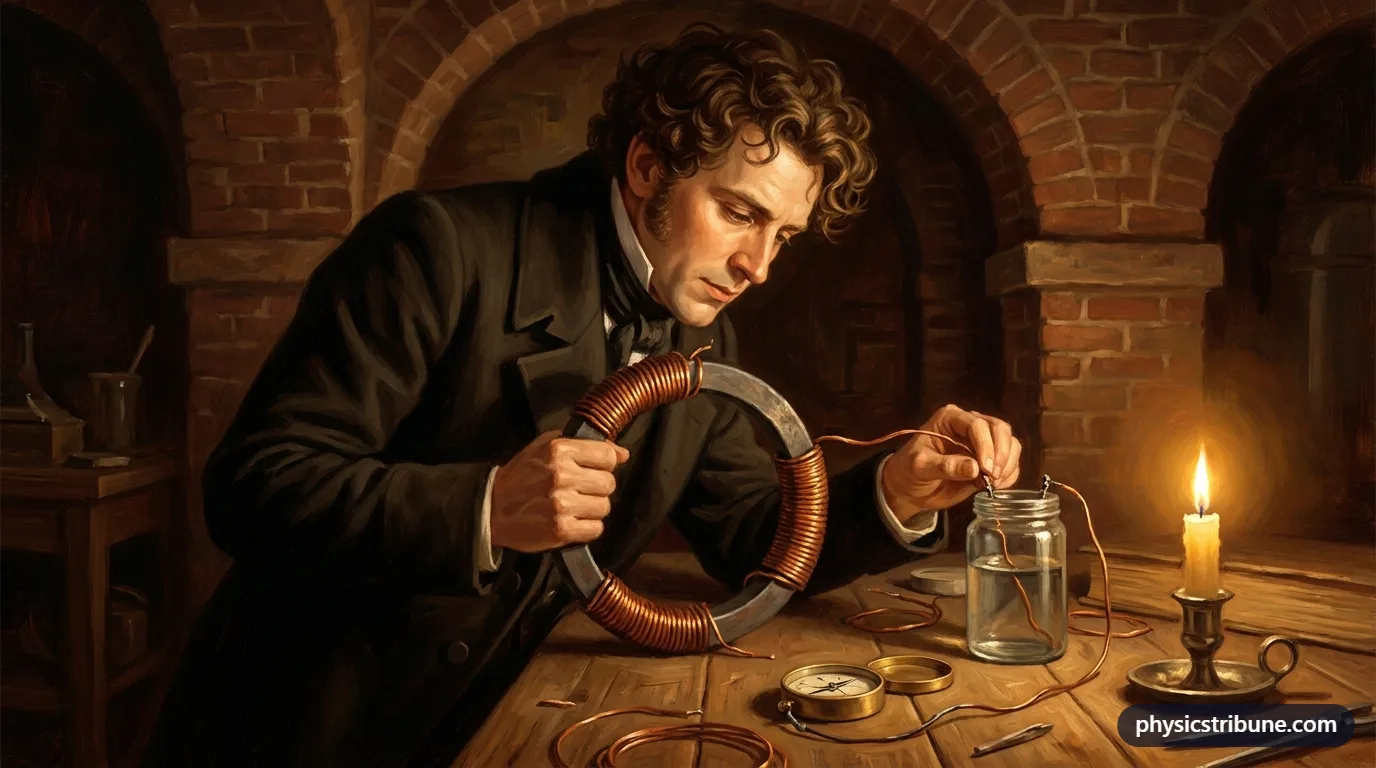
In 1833 Michael Faraday noticed that silver sulfide conducted better as it got hotter, the opposite of metals. It was an early sign of semiconducting behavior, long before anyone could explain it.
Photoconductivity was found in 1873, when the English engineer Willoughby Smith, testing selenium rods for undersea telegraph work, saw their resistance drop in light. Practical thermistors made from metal oxides followed in the 1930s and 1940s, and cadmium sulfide photocells became common in camera light meters and lighting controls in the mid twentieth century.
Key Facts
- A thermistor is a resistor whose resistance changes strongly with temperature.
- An NTC thermistor's resistance falls as temperature rises, by roughly four percent per degree near room temperature.
- A PTC thermistor's resistance rises sharply above a switching temperature, which makes it useful as a resettable fuse.
- An LDR's resistance falls as light gets brighter, from around a megaohm in darkness to hundreds of ohms in bright light.
- Thermistors and LDRs are usually placed in a voltage divider so that a change in resistance becomes a change in voltage.
- Both components are non-ohmic, because their resistance depends on conditions other than the applied voltage.
- Photoconductivity was discovered in selenium in 1873, and practical oxide thermistors followed in the 1930s and 1940s.
Quick Quiz: How Well Do You Know Thermistors and Light-Dependent Resistors (LDRs)?
6 questions. Tap an answer to check it.
What happens to the resistance of an NTC thermistor as it gets hotter?
Heat frees more charge carriers in the semiconductor, so resistance falls.
When is an LDR's resistance highest?
With no light freeing charge carriers, the LDR barely conducts.
A divider has a 10 kΩ fixed resistor on top and a 10 kΩ thermistor at the bottom on a 6 V supply. What is the voltage across the thermistor?
Equal resistances share the supply equally, so each gets 3 V.
Which device is commonly used as a resettable fuse?
A PTC device jumps to high resistance when overloaded and recovers when it cools.
What physical effect makes an LDR work?
Light frees charge carriers in the semiconductor, lowering its resistance.
Why do thermistor circuits keep the sensing current small?
Self-heating would lower the resistance and make the reading too warm.
Frequently Asked Questions
What is the difference between a thermistor and an LDR?
Both are resistors whose resistance changes with their surroundings, but they respond to different things. A thermistor responds to temperature, and the common NTC type loses resistance as it warms. An LDR responds to light, and its resistance falls as the light gets brighter. Each is usually used in a voltage divider to produce a voltage that tracks temperature or light level.
What happens to the resistance of a thermistor when the temperature increases?
For an NTC thermistor, the most common type, resistance decreases as temperature increases, because heat frees more charge carriers in its semiconducting material. A typical 10 kΩ part drops to around 3.6 kΩ at 50 °C. For a PTC thermistor the opposite happens: resistance rises, slowly at first and then very steeply above its switching temperature.
What happens to the resistance of an LDR in the dark?
In the dark an LDR's resistance becomes very high, typically around a megaohm or more, because almost no light is freeing charge carriers in it. As light returns, its resistance falls quickly, reaching a few hundred ohms in bright light. This large swing is what lets a simple LDR circuit switch a night light or streetlight on and off.
Is a thermistor ohmic or non-ohmic?
A thermistor is non-ohmic. Its resistance depends on temperature, so if the current through it warms it up, its resistance changes and its I-V graph curves. At a fixed temperature and a very small current, it behaves almost like an ordinary resistor, which is why sensing circuits keep the current tiny to avoid self-heating errors.
What does NTC and PTC mean?
NTC stands for negative temperature coefficient: resistance goes down as temperature goes up. PTC stands for positive temperature coefficient: resistance goes up as temperature goes up. NTC thermistors are mostly used for measuring temperature and limiting switch-on surges, while PTC thermistors are mostly used as resettable fuses, motor protection and self-regulating heaters.
Why is a thermistor used in a voltage divider?
Circuits such as microcontrollers and comparators read voltages, not resistances. Placing the thermistor in series with a fixed resistor across a supply makes the voltage at the junction depend on the thermistor's resistance. As the temperature changes, that voltage changes, and the circuit can convert it back into a temperature using a calibration curve or a formula.
What are LDRs made of?
Most traditional LDRs are made of cadmium sulfide, sometimes with cadmium selenide, laid down as a thin wavy track between two metal contacts. The wavy shape gives a long, narrow path that exposes plenty of material to light. Because cadmium is toxic and restricted in many places, newer light sensors often use silicon photodiodes or phototransistors instead.
Keep Exploring
 electricityVoltage Divider
 calculatorsVoltage Divider Calculator
 electricityOhmic and Non-Ohmic Conductors (I-V Characteristics)
 electricitySemiconductors and Doping
 electricityResistors
 electricityWheatstone Bridge
 thermodynamicsHow Thermometers Work
 physicistsMichael Faraday
 worksheetsElectricity Worksheets